|
|
| Ammeters
and Voltmeters |
|
|
The device which measure current and potential difference
in circuit are called ammeters and voltmeters respectively.
The
basic component of these meters is the moving coil galvanometer.
But before we discuss how a moving coil galvanometer is converted
into an ammeter or voltmeter, let us see how these meters
are connected in a circuit. |
|
|
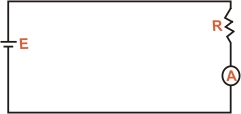
(I) Ammeter : An ammeter is connected in series
with the circuit element whose current we wish to measure.
It is because only then current through the circuit element
also goes through the ammeter. Thus, in order to measure current
through resistor R in fig (a), we place an ammeter in series
with the resistor. |
|
| |
Fig
(a) |
|
|
An ammeter should have a very
low resistance so that on connecting it in the circuit, there
is negligible change in the circuit resistance (and hence
the circuit current). |
|
|
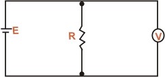
(II) Voltmeter :
A voltmeter is connected in parallel with the circuit component
across which potential difference is to be measured. It is
because potential difference (or voltmeter) refers to two
points. So to measure the potential difference between two
points in a circuit, we connect the two terminals of the voltmeter
to those points. Thus to measure the voltmeter across resistance
R fig (b), we connect the two terminals of the voltmeter to
the two ends of the resistors. |
|
| |
Fig
(b) |
|
|
The voltmeter should have a very
high resistance so that on connecting it in the circuit, there
is negligible change in the circuit resistance (and hence
the circuit current). |
|